When it comes to precision in automotive repair and assembly, the dial indicator is an indispensable tool. From measuring runout on rotating components to ensuring perfect backlash during ring and pinion gear installation, this precision instrument plays a critical role in ensuring optimal driveline performance. In this guide, we’ll walk through everything you need to know about using a dial indicator, especially for bevel gear applications like crown wheel and pinion gears.
What Is a Dial Indicator?
A dial indicator is a high-precision measuring tool designed to detect and display small linear distances. It works through a plunger that moves in and out in response to changes in surface height or movement, converting this motion into dial readings.
Common uses include:- Measuring backlash in gear systems (e.g., ring and pinion sets)
- Checking runout in shafts, wheels, and rotors
- Verifying flatness and alignment in machined surfaces
- Measuring endplay and gear wear
Components of a Dial Indicator
Before using a dial indicator, it’s important to understand its parts:
- Magnetic base: Attaches the tool firmly to metal surfaces such as differential housings.
- Adjustable arms: Allow positioning at various angles to reach gear teeth.
- Plunger (probe): Moves in and out as it contacts the surface, transmitting movement to the dial.
- Main dial: Measures displacement in thousandths of an inch.
- Revolution counter: Tracks how many times the main needle has revolved.

How to Set Up a Dial Indicator
Correct setup is critical to getting accurate and repeatable measurements.
1. Secure the Base
Mount the magnetic base on a clean, stable metal surface. For gear setup, the differential housing is often used.
2. Position the Arm
Adjust the armature so the tip of the plunger rests at a 90-degree angle on the surface to be measured (e.g., ring gear tooth face).
3. Align the Plunger
Make sure the plunger’s motion is in line with the gear’s movement. Misalignment causes measurement errors.
4. Eliminate Flex and Play
Tighten all adjustments and verify the setup is stable. Any movement or slack will cause false readings.
5. Zero the Dial
Rotate the dial face so the needle points to zero before starting measurements.
Measuring Backlash in Ring and Pinion Gears
Backlash is the amount of play between the teeth of the ring gear and the pinion. This measurement is essential to ensure proper gear meshing:
- Too little backlash can cause excessive heat, noise, and gear binding.
- Too much backlash leads to gear rattle, premature wear, and power loss.

Detailed Steps to Measure Backlash:
- Install the ring and pinion gears in the differential housing as per the manufacturer’s preliminary setup.
- Secure the dial indicator on the housing using a magnetic base.
- Place the plunger tip on the drive side of a ring gear tooth at a 90-degree angle.
- Zero the dial by rotating it so the needle rests at zero.
- Stabilize the pinion gear to prevent it from moving during measurement (clamp or hold it securely).
- Gently rotate the ring gear back and forth. This movement represents the gear’s free play.
- Observe the needle movement. This is your backlash reading.
Backlash readings are typically between 0.006″ to 0.010″ depending on the axle and application. Always refer to the manufacturer’s specifications.
Want to dive deeper into backlash? Read our in-depth guide: How to Set Ring and Pinion Backlash?
Pro Tip:
Take several measurements on multiple teeth around the ring gear. If values vary significantly, it may indicate gear misalignment or improper housing bore concentricity.
Measuring Runout and Gear Face Irregularities
Runout is a condition where a rotating component wobbles due to an imperfect circle or uneven mounting. It’s important to check runout on:
- Ring gear face
- Brake rotors
- Axles
- Set the indicator tip against the rotating surface.
- Rotate the component slowly.
- Measure the highest and lowest needle positions.
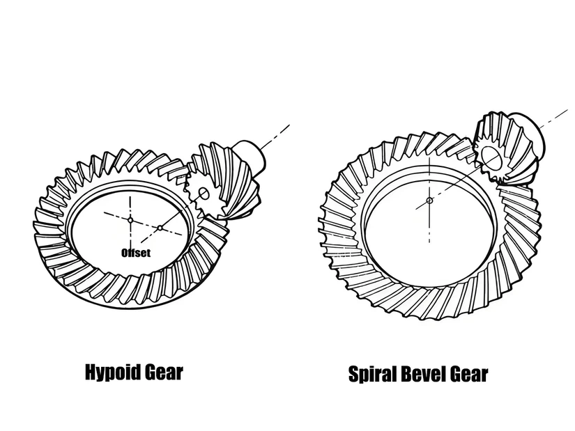
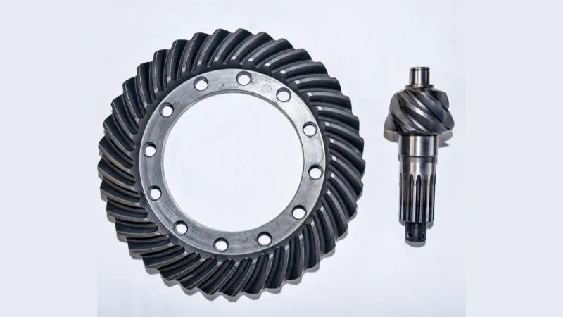
Application in Ring and Pinion Gear Setup
In the context of bevel gear installation—especially crown wheel and pinion gears used in differentials—a dial indicator ensures precise adjustment and alignment.
Key Applications Include:- Backlash Tuning: Matching gear teeth clearance using shims to prevent premature wear.
- Gear Runout Inspection: Ensuring ring gear seats evenly on the carrier.
- Bearing Preload Check: Indirectly aids in confirming bearing preload by measuring rotational drag after assembly.
- Tooth Contact Pattern Correction: While this is mainly visual (using gear marking compound), backlash measured via dial indicator directly influences the contact patch.
Tips for Accurate Results in Bevel Gear Work
- Always Stabilize the Pinion: Movement in the pinion gear during backlash measurement can distort results.
- Clean All Surfaces: Debris or oil between the magnetic base and housing can introduce flex.
- Use Consistent Force: Rotate the ring gear gently to avoid jolts that affect needle movement.
- Measure Multiple Points: Especially on large ring gears, readings should be averaged from different locations.
- Avoid Adjacent Tooth Interference: Make sure the plunger touches only one tooth.
- Torque All Components Properly: Pre-torque the carrier bearing caps before final measurement to simulate operational conditions.
- Avoid Tool Flex: Use a high-quality dial indicator with a sturdy base and armature.
Reading the Dial: Understanding the Results
Most dial indicators measure in 0.001″ increments. A full rotation of the main needle is usually 0.100″, with a smaller revolution counter tracking the total movement.
Example:
If the needle makes 2 full turns and lands at 0.030, the total movement is 0.230″.
When measuring backlash, you’re interested in total movement between gear reversals:
If the needle swings from +0.005″ to -0.010″, the backlash is 0.015″.
Final Thoughts
A dial indicator is not just a measurement tool—it’s a quality control instrument. In the high-precision world of differential gear setups, it enables mechanics and gear specialists to fine-tune clearances, prevent failure, and deliver reliable performance.
When working with ring and pinion gears, especially in demanding applications like off-road or performance vehicles, precision isn’t a luxury—it’s a necessity. With a properly used dial indicator, every gear install becomes a long-lasting success.
Frequently Asked Questions (FAQ)
Q1: Can I use a dial indicator to set preload on differential bearings?
A: While preload is typically set using torque values, a dial indicator can be used to verify bearing endplay or confirm consistent resistance during rotation, which indirectly supports proper preload setup.
Q2: What is the ideal backlash setting for most ring and pinion gears?
A: This varies by manufacturer, but most setups require backlash between 0.006″ to 0.010″. Always consult the spec sheet for your specific axle.
Q3: Is a digital dial indicator better than analog for gear work?
A: Both are effective. Analog offers a visual sweep that’s easier to monitor in real time, while digital indicators can provide faster reading and more precision in some cases.
Q4: How often should I calibrate my dial indicator?
A: Calibration should be done regularly depending on frequency of use—ideally every 6-12 months, or sooner if the tool is dropped or exposed to impact.
Q5: Can I use a dial indicator on non-automotive components?
A: Absolutely. Dial indicators are versatile tools used in machining, fabrication, and other industries where precision measurements are critical.